Galvanometer
|
|
A galvanometer is an electromechanical transducer. It produces a rotary motion, through a limited arc, in response to electric current flowing through its coil. The name galvanometer has been applied to devices used in measuring, recording, and positioning equipment.
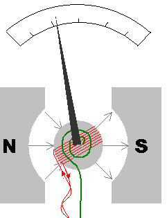
The most familiar use is as an analog measuring instrument, often called a meter. It is used to measure the direct current (flow of electric charges) through an electric circuit. Such devices are constructed with a small pivoting coil of wire in the field of a permanent magnet. The coil is attached to a thin pointer that traverses a calibrated scale. A tiny spring pulls the coil and pointer to the zero position. In some meters, the magnetic field acts on a small piece of iron to perform the same effect as a spring.
When a direct current (DC) flows through the coil, the coil generates a magnetic field. This field acts with or against the permanent magnet. The coil pivots, pushing against the spring, and moving the pointer. The hand points at a scale indicating the electric current. A useful meter generally contains some provision for damping the mechanical resonance of the moving coil and pointer so that the pointer position smoothly tracks the current without excess vibration.
The basic sensitivity of a meter might be, for instance, 100 microamperes full scale (with a voltage drop of, say, 50 millivolts at full current). Such meters are often calibrated to read some other quantity that can be converted to a current of that magnitude. The use of current dividers, often called shunts, allows a meter to be calibrated to measure larger currents. A meter can be calibrated as a DC voltmeter if the resistance of the coil is known by calculating the voltage required to generate a full scale current. A meter can be configured to read other voltages by putting it in a voltage divider circuit. This is generally done by placing a resistor in series with the meter coil. A meter can be used to read resistance by placing it in series with a known voltage (a battery) and an adjustable resistor. In a preparatory step, the circuit is completed and the resistor adjusted to produce full scale deflection. When an unknown resistor is placed in series in the circuit the current will be less than full scale and an appropriately-calibrated scale can display the value of the previously-unknown resistor.
Because the pointer of the meter is usually a small distance above the scale of the meter, parallax error can occur when the operator attempts to read the scale line that "lines up" with the pointer. To counter this, some meters include a mirror along the markings of the principal scale. The accuracy of the reading from a mirrored scale is improved by moving the head while reading the scale so that the pointer and the reflection of the pointer are aligned; at this point, the operator's eye must be directly above the pointer and any parallax error has been minimized.
Extremely sensitive measuring equipment once used mirror galvanometers that substituted a mirror for the pointer. A beam of light reflected form the mirror acted as a long, massless pointer. Such instruments were used as receivers for early trans-atlantic telegraph systems, for instance. The moving beam of light could also be used to make a record on a moving photographic film, producing a graph of current versus time, in a device called an oscillograph.
Galvanometer mechanisms have been used to position the pens of analog chart recorders. Strip chart recorders with galvanometer driven pens might have a full scale frequency response of 100 Hz and several cm deflection. In some cases (the classical polygraph of movies or the electroencephalograph), the galvanometer is strong enough to move the pen while it remains in contact with the paper; the writing mechanism may be a heated tip on the needle writing on heat-sensitive paper or a fluid-fed pen. In other cases (the Rustrak recorders), the needle is only intermittently pressed against the writing medium; at that momemnt, an impression is made and then the pressure is removed, allowing the needle to move to a new position and the cycle repeats. In this case, the galvanometer need not be especially strong.
Mirror galvanometer systems are used as beam positioning elements in laser optical systems. These are typically high power galvanometer mechanisms used with closed loop servo control systems. They can have frequency responses over 1 kHz.
Galvanometers have been replaced as measuring instruments by analog to digital converters (ADC) for most uses. There are, for instance, self contained digital measuring systems, called digital panel meters (DPMs), available to replace most traditional analog meter functions. Many computer systems also employ ADC's .
The term "galvanometer" derives from the name of Luigi Galvani. Many early applications of galvanometers for measuring and recording are associated with William Thomson (Lord Kelvin).
See also
- Electrometer
- Electricity
- Electronics
- Electric current
- Electric charge
- Electrical quackeryde:Galvanometer
es:Galvanómetro fr:Galvanomètre nl:Galvanometer pl:Galwanometr

