Space shuttle main engine
|
|
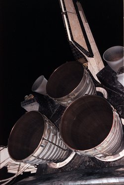
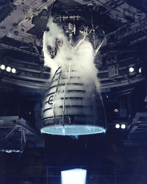
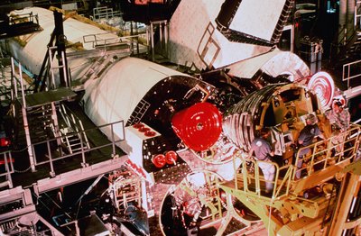
The Space Shuttle orbiter has three main engines (SSMEs). They are very sophisticated power plants that burn liquid hydrogen with liquid oxygen, both from the Space Shuttle external tank. They are used for propulsion during its ascent, in addition to the two more powerful Solid Rocket Boosters. Each engine can generate almost 400,000 pounds (1.8 MN) of thrust at liftoff. The engines are removed every flight and taken to a shop in the Vehicle Assembly Building for inspection and replacement of any necessary components.
The Space Shuttle's rocket engines are capable of operating at extreme temperatures. The liquid hydrogen fuel is stored at minus 423 degrees Fahrenheit (-253 degrees Celsius). However, when burned with liquid oxygen, the temperature in the combustion chamber reaches 6,000 °F (3,300 °C), higher than the boiling point (thus beyond the melting point) of iron. If the main engines pumped water instead of liquid oxygen and liquid hydrogen, an average family-sized swimming pool could be drained in 25 seconds.
Apart from the three main engines, the orbiter has 44 smaller rockets around the orbiter's surface, which are part of the Orbital Maneuvering and Reaction Control systems, used to provide steering, pointing, and attitude adjustment capability while in orbit.
The engines perform as follows: Oxidizer from the external tank enters the orbiter at the orbiter/external tank umbilical disconnect and then the orbiter's main propulsion system liquid oxygen feed line. There it branches out into three parallel paths, one to each engine. In each branch, a liquid oxygen prevalve must be opened to permit flow to the low-pressure oxidizer turbopump.
The Low Pressure Oxidizer Turbopump (LPOT) is an axial-flow pump driven by a six-stage turbine powered by liquid oxygen. It boosts the liquid oxygen's pressure from 100 to 422 psia (0.7 to 2.9 MPa). The flow from the LPOT is supplied to the High-Pressure Oxidizer Turbopump (HPOT). During engine operation, the pressure boost permits the High Pressure Oxidizer Turbine to operate at high speeds without cavitating. The LPOT operates at approximately 5,150 rpm. The LPOT, which is approximately 18 by 18 inches (450 by 450 mm), is connected to the vehicle propellant ducting and supported in a fixed position by the orbiter structure.
The HPOT consists of two single-stage centrifugal pumps (a main pump and a preburner pump) mounted on a common shaft and driven by a two-stage, hot-gas turbine. The main pump boosts the liquid oxygen's pressure from 422 to 4,300 psia (2.9 to 30 MPa) while operating at approximately 28,120 rpm. The HPOT discharge flow splits into several paths, one of which is routed to drive the LPOT turbine. Another path is routed to and through the main oxidizer valve and enters into the main combustion chamber. Another small flow path is tapped off and sent to the oxidizer heat exchanger. The liquid oxygen flows through an anti-flood valve that prevents it from entering the heat exchanger until sufficient heat is present to convert the liquid oxygen to gas. The heat exchanger utilizes the heat contained in the discharge gases from the HPOT turbine to convert the liquid oxygen to gas. The gas is sent to a manifold and is then routed to the external tank to pressurize the liquid oxygen tank. Another path enters the HPOT second-stage preburner pump to boost the liquid oxygen's pressure from 4,300 psia to 7,420 psia (30 to 51 MPa). It passes through the oxidizer preburner oxidizer valve into the oxidizer preburner and through the fuel preburner oxidizer valve into the fuel preburner. The HPOT is approximately 24 by 36 inches (600 by 900 mm). It is attached by flanges to the hot-gas manifold.
Fuel enters the orbiter at the liquid hydrogen feed line disconnect valve, then flows into the orbiter gaseous hydrogen feed line manifold and branches out into three parallel paths to each engine. In each liquid hydrogen branch, a prevalve permits liquid hydrogen to flow to the low-pressure fuel turbopump when the prevalve is open.
The Low Pressure Fuel Turbopump (LPFT) is an axial-flow pump driven by a two-stage turbine powered by gaseous hydrogen. It boosts the pressure of the liquid hydrogen from 30 to 276 psia (0.2 to 1.9 MPa) and supplies it to the High-Pressure Fuel Turbopump (HPFT). During engine operation, the pressure boost provided by the LPFT permits the HPFT to operate at high speeds without cavitating. The LPFT operates at approximately 16,185 rpm. The LPFT is approximately 18 by 24 inches (450 by 600 mm). It is connected to the vehicle propellant ducting and is supported in a fixed position by the orbiter structure 180 degrees from the LPOT.
The HPFT is a three-stage centrifugal pump driven by a two-stage, hot-gas turbine. It boosts the pressure of the liquid hydrogen from 276 to 6,515 psia (1.9 to 45 MPa). The HPFT operates at approximately 35,360 rpm. The discharge flow from the turbopump is routed to and through the main valve and then splits into three flow paths. One path is through the jacket of the main combustion chamber, where the hydrogen is used to cool the chamber walls. It is then routed from the main combustion chamber to the LPFT, where it is used to drive the LPFT turbine. A small portion of the flow from the LPFT is then directed to a common manifold from all three engines to form a single path to the external tank to maintain liquid hydrogen tank pressurization. The remaining hydrogen passes between the inner and outer walls to cool the hot-gas manifold and is discharged into the main combustion chamber. The second hydrogen flow path from the main fuel valve is through the engine nozzle (to cool the nozzle). It then joins the third flow path from the chamber coolant valve. The combined flow is then directed to the fuel and oxidizer preburners. The HPFT is approximately 22 by 44 inches. It is attached by flanges to the hot-gas manifold.
The oxidizer and fuel preburners are welded to the hot-gas manifold. The fuel and oxidizer enter the preburners and are mixed so that efficient combustion can occur. The augmented spark igniter is a small combination chamber located in the center of the injector of each preburner. The two dual-redundant spark igniters, which are activated by the engine controller, are used during the engine start sequence to initiate combustion in each preburner. They are turned off after approximately three seconds because the combustion process is then self-sustaining. The preburners produce the fuel-rich hot gas that passes through the turbines to generate the power to operate the high-pressure turbopumps. The oxidizer preburner's outflow drives a turbine that is connected to the HPOT and the oxidizer preburner pump. The fuel preburner's outflow drives a turbine that is connected to the HPFT.
The HPOT turbine and HPOT pumps are mounted on a common shaft. Mixing of the fuel-rich hot gas in the turbine section and the liquid oxygen in the main pump could create a hazard. To prevent this, the two sections are separated by a cavity that is continuously purged by the MPS engine helium supply during engine operation. Two seals minimize leakage into the cavity. One seal is located between the turbine section and the cavity, and the other is between the pump section and cavity. Loss of helium pressure in this cavity results in an automatic engine shutdown.
The speed of the HPOT and HPFT turbines depends on the position of the corresponding oxidizer and fuel preburner oxidizer valves. These valves are positioned by the engine controller, which uses them to throttle the flow of liquid oxygen to the preburners and, thus, control engine thrust. The oxidizer and fuel preburner oxidizer valves increase or decrease the liquid oxygen flow, thus increasing or decreasing preburner chamber pressure, HPOT and HPFT turbine speed, and liquid oxygen and gaseous hydrogen flow into the main combustion chamber, which increases or decreases engine thrust, thus throttling the engine. The oxidizer and fuel preburner valves operate together to throttle the engine and maintain a constant 6-1 propellant mixture ratio.
The main oxidizer valve and the main fuel valve control the flow of liquid oxygen and liquid hydrogen into the engine and are controlled by each engine controller. When an engine is operating, the main valves are fully open.
A coolant control valve is mounted on the combustion chamber coolant bypass duct of each engine. The engine controller regulates the amount of gaseous hydrogen allowed to bypass the nozzle coolant loop, thus controlling its temperature. The chamber coolant valve is 100 percent open before engine start. During engine operation, it will be 100 percent open for throttle settings of 100 to 109 percent for minimum cooling. For throttle settings between 65 to 100 percent, its position will range from 66.4 to 100 percent open for maximum cooling.
Each engine main combustion chamber receives fuel-rich hot gas from a hot-gas manifold cooling circuit. The gaseous hydrogen and liquid oxygen enter the chamber at the injector, which mixes the propellants. A small augmented spark igniter chamber is located in the center of the injector. The dual-redundant igniter is used during the engine start sequence to initiate combustion. The igniters are turned off after approximately three seconds because the combustion process is self-sustaining. The main injector and dome assembly is welded to the hot-gas manifold. The main combustion chamber also is bolted to the hot-gas manifold.
The inner surface of each combustion chamber, as well as the inner surface of each nozzle, is cooled by gaseous hydrogen flowing through coolant passages. The nozzle assembly is a bell-shaped extension bolted to the main combustion chamber. The nozzle is 113 inches (2.9 m) long, and the outside diameter of the exit is 94 inches (2.4 m). A support ring welded to the forward end of the nozzle is the engine attach point to the orbiter-supplied heat shield. Thermal protection for the nozzles is necessary because of the exposure that portions of the nozzles experience during the launch, ascent, on-orbit and entry phases of a mission. The insulation consists of four layers of metallic batting covered with a metallic foil and screening.
The five propellant valves on each engine (oxidizer preburner oxidizer, fuel preburner oxidizer, main oxidizer, main fuel, and chamber coolant) are hydraulically actuated and controlled by electrical signals from the engine controller. They can be fully closed by using the MPS engine helium supply system as a backup actuation system.
The low-pressure oxygen and low-pressure fuel turbopumps are mounted 180 degrees apart on the orbiter's aft fuselage thrust structure. The lines from the low-pressure turbopumps to the high-pressure turbopumps contain flexible bellows that enable the low-pressure turbopumps to remain stationary while the rest of the engine is gimbaled for thrust vector control. The liquid hydrogen line from the LPFT to the HPFT is insulated to prevent the formation of liquid air.
The main oxidizer valve and fuel bleed valve are used after shutdown. The main oxidizer valve is opened during a propellant dump to allow residual liquid oxygen to be dumped overboard through the engine, and the fuel bleed valve is opened to allow residual liquid hydrogen to be dumped through the liquid hydrogen fill and drain valves overboard. After the dump is completed, the valves close and remain closed for the remainder of the mission.
The gimbal bearing is bolted to the main injector and dome assembly and is the thrust interface between the engine and orbiter. The bearing assembly is approximately 11.3 by 14 inches (287 by 356 mm).
Overall, a space shuttle main engine weighs approximately 7,000 pounds (3.2 t).
See also
- MPTA-098 - the SSME test article used in Shuttle development


