Caplock mechanism
|
|
The caplock mechanism was the successor of the flintlock mechanism in firearm technology, and used a percussion cap struck by the hammer to set off the main charge, rather than using a piece of flint to strike a steel frizzen.
Terminology
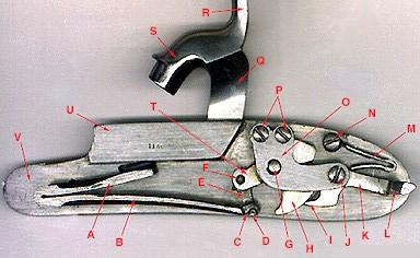
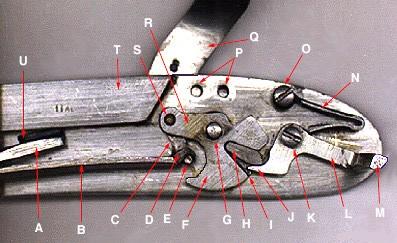
The following photographs show both sides of the caplock mechanism, along with descriptions of the annotated parts.
External side of the lock:
Missing image
Percterm-E.jpg
Image:percterm-E.jpg
A- Mainspring retainer stud B- Lockplate C- Hammer nose recess D- Hammer head E- Hammer spur F- Hammer G- Tumbler screw H- Sear spring screw tip
Internal side of the lock:
A- Upper limb of mainspring B- Lower limb of mainspring C- Claw of mainspring D- Lower pivot stud of stirrup E- Stirrup F- Upper pivot stud of stirrup G- Tumbler axle/pivot H- Tumbler I- Pawl of sear (sear nose) J- Sear pivot screw K- Body of the sear L- Arm of the sear M- Sear spring N- Sear spring screw O- Bridle P- Bridle screws Q- Hammer R- Hammer spur S- Hammer head T- Stirrup arm of tumbler U- Bolster V- Lockplate
Internal side of the lock, with bridle removed:
A- Upper limb of mainspring B- Lower limb of mainspring C- Stirrup D- Claw of mainspring E- Lower pivot stud of stirrup F- Tumbler G- Tumbler axle/pivot H- Fly I- Half-cock notch of tumbler J- Pawl of sear (sear nose) K- Sear pivot screw L- Body of the sear M- Arm of sear N- Sear spring O- Sear spring screw P- Bridle screw holes Q- Hammer R- Stirrup arm of tumbler S- Upper pivot stud of stirrup T- Bolster U- Retainer stud of mainspring


